About
Note: article updated February 2014 to fix a fundamental mistake in the calculations and update the application notes with more realistic data.
A current source is the dual of a voltage source – it delivers a constant current, regardless of the voltage. While a resistor can be used as a rough current source, the current drawn will vary with the voltage. (Ohm’s law stipulates that I = V/R. The resistance is constant so if the voltage increases, current flow also increases. Same applies for decreases).
This project is based on the common LM317T regulator, used as a current regulator. The circuit is ideal for driving LED arrays, laser diodes or any other circuit requiring a constant current supply. Alternatively, this could also be used as an electronic dummy load for testing small power supplies at relatively low current levels. Suggested applications and all calculations are explained in this article.
Parts List
These are common parts, and should be available for <$8 at any good electronics component store.
| Qty | Part | Comments |
|---|---|---|
| 1 | LM317T | ‘T’ signifies TO-220. Other packages also suitable. |
| 1 | 0.1µF (100nF) Capacitor | MKT or Ceramic Disc |
| 1 | 47µF Capacitor | Electrolytic – voltage depends on application |
| 1 | Resistor OR Trimpot | See application notes |
| 1 | Heatsink | Size depends on current, refer to article |
Schematic

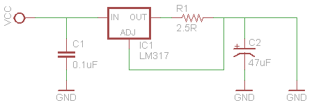
Tip: the terminals of the actual regulator may not match the pins on the schematic. Often, they are rearranged for ease of understanding! In this case, the terminals of the LM317T (when viewed head on) are actually Adj, Out, and In, despite being labeled as In, Adj and Out on the circuit diagram.
How it works
The main component in this circuit is the LM317T voltage regulator. It is a versatile component, able to supply 1.5A+ even at elevated temperatures, is highly stable, has built in current limiting, safe operating area and over-temperature shut down. Resistor R1 is placed in series with the output terminal of the LM317. The adjust terminal of the LM317 is connected in parallel to R1. During normal operation, the IC will maintain the voltage present at the adjust terminal at 1.25V, so the voltage across R1 is in turn 1.25V. With changes in current, the voltage drop across R1 would normally increase or decrease but the LM317 rapidly adjusts the output voltage to compensate, keeping the voltage drop across R1 at a constant 1.25V. By selecting the value of R1, we can take advantage of this behaviour to set a ‘limit’ on the current supplied by the regulator. Using Ohm’s law:
R = Vref / I
where R is the resistance in ohms, Vref is the reference voltage at the adjust pin (1.25V) and I is the current in amps. As R1 is connected in series with the output of the regulator, it will dissipate some of the electrical energy as heat. As well as selecting the value of the resistor, we must also select a suitable power rating to avoid burning it out. To calculate the power dissipated:
P = Vref * I
where P is power in watts, Vref is 1.25V (as previously mentioned) and I is the current previously selected. Resistors come in standard power ratings (0.125W, 0.25W, 0.5W, 1W, 2W, 5W), so pick a resistor that has a higher rating than the calculated power. Leave a margin of safety, so if your calculated power is 0.48W, consider picking a 1W resistor over a 0.5W resistor. The LM317 has a dropout voltage of ~ 1.5V to 2.5V, depending on the current being supplied and the temperature. This means that the output voltage will always be lower than the input voltage, so you need to have a supply voltage higher than target output voltage. Assuming worst case scenario, we use a figure of 2.5V in calculations. Calculating the power wasted (and in turn heat generated) by the regulator is slightly more complex than the calculations for a simple resistor.
P = (Vin – Vf) * I
where P is power in watts, Vin is the input voltage , Vref is 1.25V, Vf is the voltage drop of the connected load and I is the current in amps. Depending on the current being supplied, you may need a heatsink to help dissipate the generated heat or the LM317 will shut down automatically to protect itself from overheating. The 0.1µF capacitor is included to bypass the input, and the 47µF capacitor is connected in parallel across the output to ensure stability of the regulator. Simply put, they improve the performance of the circuit. It is possible to omit the capacitors entirely (especially if you are integrating this circuit into another project), but it helps prevent any problems that may occur.
Application Notes
There are some practical limitations that apply to this circuit which affect it’s permissible current output and resistor value selection. The LM317 has a minimum operating current of 10mA and a guaranteed minimum output current of 1.5A. As a result, the resistor value chosen must be between 0.83 ohms, and 125 ohms. If R1 is less than 0.83 ohms, more than 1.5A of current will be sourced and the LM317 will begin to approach the limit of it’s safe operation. If R1 is greater than 125 ohms, the regulator may fail to regulate the current.
The maximum current R1 should have to dissipate when the LM317 is pushed to its limit (~2.0A) is 2.5W. If your current source is expected to operate at 1.5A+ periodically, for extended periods above 1.2A, or your circuit is operating in at an elevated temperature (eg, a sealed enclosure) consider using a 5W resistor for long term reliability. If you are using a 1 or 2W resistor, mount it above the PCB such that there is a 1-2mm gap underneath for airflow.
 While the LM317 is able to operate at up to 125°C sustained, it’s lifespan is shortened and it becomes a burn or fire hazard to anything that may come into contact with it. It is recommended that a heatsink is fitted to aid cooling. According to the manufacturers datasheet, the LM317 has a junction-to-ambient thermal resistance of 50°C/W and a junction-to-case thermal resistance of 4°C/W. This means that for every 1 watt of power than needs to be dissipated, the IC will rise 50°C above the ambient temperature (typically 25°C). In a typical circuit where the current source might be driving an array of 20+ LEDs, it is not atypical for up to 3W of heat to be generated. The temperature the LM317 in free air will reach during operation is calculated thus:
Operating temperature = Ambient temperature + Power * Junction-to-Ambient Thermal Resistance
Operating temperature = 25°C + 3 * 50
Operating temperature = 175°C!
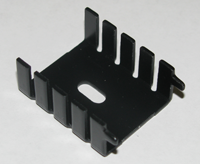
Obviously, the regulator would have shut down long before reaching 175°C, but this demonstrates that heatsinking is required for proper operation. A heatsink as small as the one shown above would be more than adequate, as it has a thermal resistance of 12°C/W.
Operating temperature = Ambient temperature + Power * (Junction-to-Case Thermal Resistance + Case to Heatsink Thermal Resistance + Heatsink Thermal Resistance)
The Case to Heatsink Thermal Resistance is highly dependent on how the LM317 is mounted. TO-220 devices which are mounted directly to the heatsink with the correct pressure and good quality thermal grease have a thermal resistance of ~0.5°C/W. TO-220 packages mounted directly without any grease are typically ~1-1.5°C/W. We shall use 1°C/W as a conservative estimate for a correctly mounted device:
Operating temperature = 25°C + 3 * (4 + 1 + 12)
Operating temperature = 76°C
This is a much more reasonable operating temperature. To minimize the amount of power wasted (and thus heat generated), keep the supply voltage as low as possible to maintain the desired output. e.g., if driving a LED array with a forward voltage of 5.2V @ 160mA, taking into account the maximum dropout voltage of the regulator (2.5V), the ideal input voltage is 9V which will only require 0.61W be dissipated. If the same circuit was powered off a 15V source, over 1.57W of power would be wasted as heat in the regulation process.
Warning! The metal tab of the LM317 is connected to the output pin so when power is applied to the circuit, the heatsink may become ‘live’ if directly attached to the regulator. Special insulating kits are available, consisting of nylon screws, nuts and washers, and non-conductive silicon-rubber or mica insulating pads to electrically isolate the regulator from the heatsink. Remember to factor in the thermal resistance of the insulating kit into your heatsink calculations!
.
Sample Circuit 1 – Driving a LED Array (or Laser Diode)
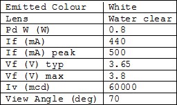
 You have 2 high brightness LEDs you want to power from a 12V car battery to use as a lamp. A sample datasheet is included on the right for reference. The most efficient way of powering the LEDs is connecting them in series to the output of the current source (see schematic). This means that the that forwards voltage is doubled to 7.3V, but the typical operating current remains the same at 440mA. Using the formulas above, we first calculate the value of R1 and then the power rating required:
R = 1.25V / 0.44A = 2.841Ω
P = 1.25V * 0.44A = 0.55W
There are no resistors of the exact value 2.841Ω available, so we have 2 options:
- Use the next closest value, a 2.7Ω resistor giving us 463mA of current
- Use a 1Ω and 1.8Ω resistor in series to approximate 2.841Ω
 Either solution is acceptable, as the slight variation in current from the ideal 440mA is insignficant, and still within the 500mA peak the LEDs would be able to handle. As the calculated power is either 0.58W or 0.56W (depending which resistor option you selected), this is over the 0.5W threshold so the next best choice is a 1W resistor. Next, we calculate the power dissipated by the LM317 to ascertain whether or not we need an external heatsink, and if so, what size. Assuming we use a 2.7Ω resistor and the LM317 is in free air:
P = (12V – 7.3V) * 0.463A = 2.176W
Operating temperature = 25°C + (50 * 2.176) = 133.8°C
The circuit will need a heatsink as 133.8°C has exceeded the operating range of the LM317. A heatsink with a thermal resistance of 21°C/W will bring the operation temperature down to 79°C. However, if it is to be used outdoors in the sun or in an enclosure without ventilation, consider fitting a heatsink which is 16°C/W thermal resistance or lower to compensate for the increased ambient temperature. If used inside a metal enclosure, simply attaching the LM317 to one of the walls or lid may be sufficient; if the enclosure is plastic and sealed, ensure their is adequate ventilation by cutting out ventilation slots. Remember, the metal tab of the regulator is connected to Vout, so make sure you use an insulating kit.
The same concept can also be used to drive a laser diode or any circuit requiring a current source. Find out the operating voltage and typical forward current required and substitute for the values above.
Sample Circuit 2 – Power Supply Electronic Dummy Load
There are more efficient and precise ways of electronically loading a power supply, but using this circuit is cheap, simple and works well for lower currents.
Why would you want to place an artificial variable load on a power supply? Placing a load on a power supply is a useful test which allows you to check it’s performance and measure factors such as ripple, min and max voltage, temperature rise and test protection systems such as thermal fuses, over-current and short circuit shut down. Similar to the resistor based current source and the LED, a rheostat (high powered variable resistor) or heating element connected to the power supply draws a current which is dependent on the output voltage. The current source circuit can be easily adapted to allow us to draw a fixed current regardless of the power supplies output voltage. Of course, we can also vary the current drawn if desired.

To present a fixed load to a power supply, simply ‘short’ the output of the resistor directly the ground/negative. This means that the ‘forward voltage’ is now effectively 0V and the ‘typical operating current’ is the amount of current you wish to draw from the power supply. In the example schematic shown (right), when connected to a power supply, the circuit would draw a load of 500mA. A 1W resistor would have to be used and as the regulator is dissipating the vast majority of the power, a substantial heatsink will be required.
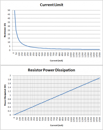
We can vary the current being sunk (drawn from the power supply) by replacing R1 with a variable resistor. This however becomes problematic, as shown by the following graphs (click to enlarge):
The resistance required to vary the current between 10mA and the full 1.5A is not linear (graph1). The variation of resistance required at high currents is minute. However, the power dissipated by the resistor varies linearly with the current sunk by the LM317. This presents a problem, as most 9, 16 and 24mm rotary potentiometers are limited to a power of 0.5W max, which would cap the current drawn by the circuit at ~400mA before catching fire. Horizontal and vertical trimpots are worse, as they can only dissipate 0.1W, which equates roughly to ~75mA. Furthermore, you would have great difficulty varying the current drawn as almost 80% of the current range is adjusted using the last 1-2 degrees of rotation.
There are several solutions to this problem:
- Use a 15-25 revolution ‘multi-turn’ precision trimmer potentiometer, ‘3006P Horizontal’ style. Unlike normal potentiometers which typically start at 1 kiloohm, they are available in 50 ohm values and each 360 degree revolution equates to 2 ohms, allowing a much finer adjustment of resistance. They are available in power ratings of 0.75W max, so this limits the current draw to 600mA. This may be acceptable if you do not require a high current draw.
- Use a high powered wirewound potentiometer. These are only available in very low resistance values, typically 5 ohms, but can handle up to 15W of power. With a total rotation angle of 300*, this allows for an adjustment of 0.017 ohms/degree. The low resistance (5 ohm) does mean that the minimum current draw is 250mA, but you are able to draw the full 1.5A+ without burning out the resistor.
- If you are lucky enough to own or come across precision laboratory rheostats, they can also be used to similar effect.
Links
Manufacturer’s datasheet (LM317)
R1 - Current, Resistance and Power Dissipation Spreadsheet (23586 downloads )